RF Transmitter · Digital Design
Generating, aligning and sequencing the switching waveforms for every amplifier in the transmit array.
The question
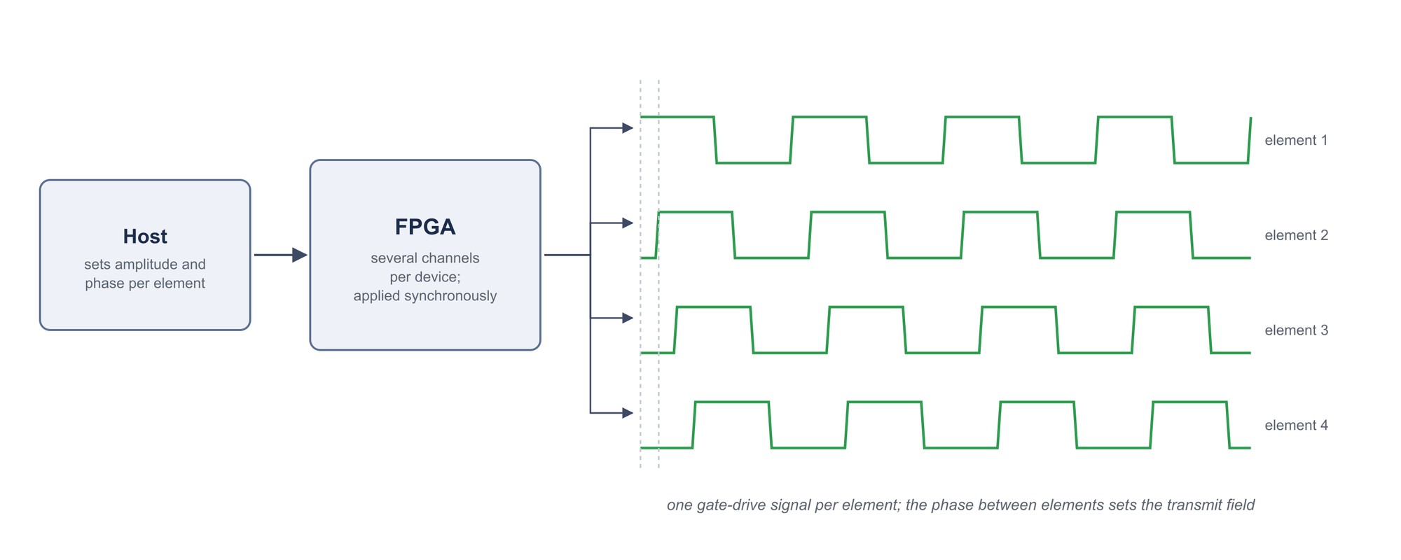
A class E amplifier is controlled entirely by when its switch opens and closes. For an array, that means generating one gate drive signal per element, with the phase relationship between elements held to a precision that the imaging sequence demands, and changed on command between pulses. This is a digital timing problem, and it is the part of the transmit chain that a commercial system never exposes.
The architecture
- FPGAs generate the gate drive signals, with several channels per device.
- Amplitude and phase per element are set from the host and applied synchronously.
- The transmitter presents the same kind of interface to the common spectrometer as the receiver and the gradient controller, so that one sequence engine drives all three chains.
The project deliberately follows the platform and conventions of the receiver project: the same family of development boards, the same hardware description language, the same host-side tooling. Sharing conventions across the three chains is what makes one person able to work on two of them.