RF Receiver · Electronics
The analog front end between the receive coil and the digital receiver, where a tenth of a decibel of noise figure is worth having.
The question
The preamplifier sets the noise floor of everything downstream. At 3 tesla the proton frequency is 123.25 MHz, and the target is a noise figure well under one decibel while presenting the impedance the coil needs for preamplifier decoupling. Commercial MRI preamplifiers reach this, but they are closed parts; we want a front end we can specify, measure and change.
Three routes in parallel
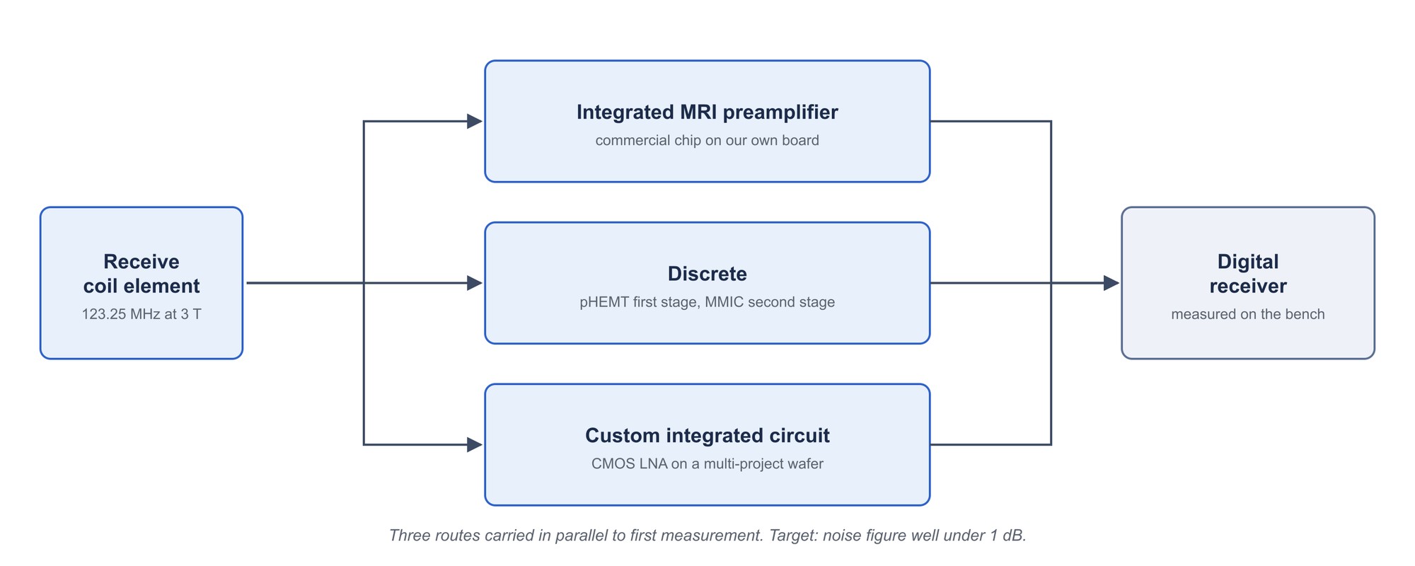
Rather than commit to one design, we are carrying three to first measurement and letting the bench decide.
| Route | Approach | Main risk |
|---|---|---|
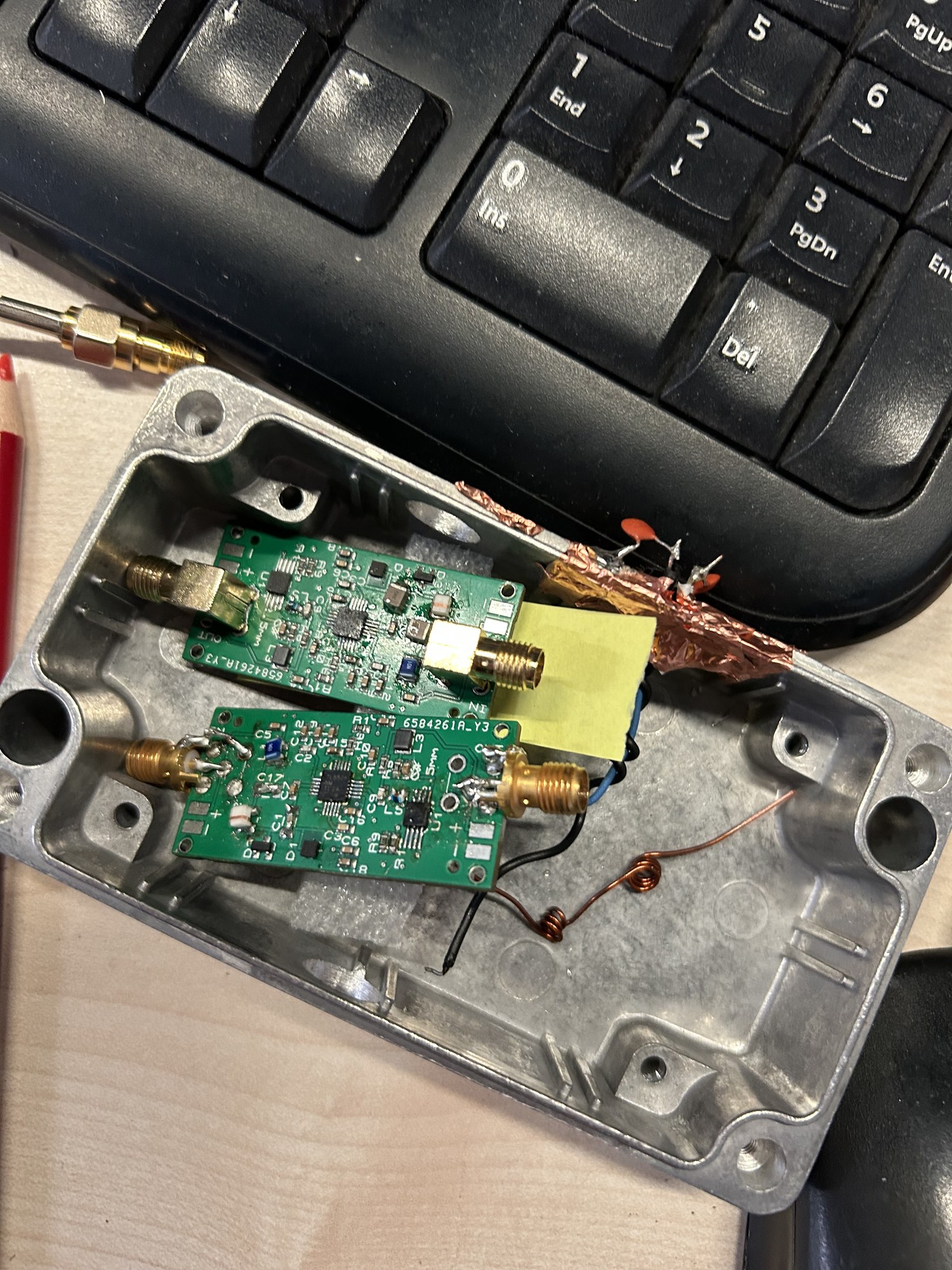
| Integrated MRI preamplifier | A commercial MRI preamplifier chip on our own board | The part is discontinued and its input impedance is unmeasured |
| Discrete | A pHEMT first stage followed by an MMIC second stage | Reaching the noise figure target through the second stage |
| Custom integrated circuit | A CMOS low-noise amplifier taped out on a multi-project wafer run | Schedule, and that fabrication is one shot |
The receiver board reserves resources for four channels, so the front end is specified four channels at a time.
Measurement
Noise figure at this level is not something to take from a datasheet. Noise measurement on our own bench, against a commercial benchmark amplifier, is part of the project rather than a check at the end.